The exact parts you need.
Microcontrollers, sensors, motors, modules, Raspberry Pi - in stock locally, quoted in hours.
- 162+
- Products in stock
- 14
- Categories
- 24h
- Quote turnaround
Built for makers, students, and labs.
Real product. Real stock. Browse, then request a quote.
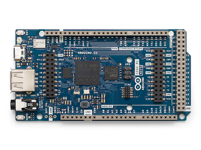
Arduino GIGA R1 WiFi
SKU L404-034 Request quote →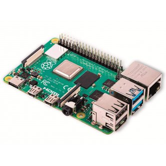
Complete kit: Raspberry Pi 4 Model B Quad Core 64 bits WiFi bluetooth (8 GB RAM)+ CASE+FAN+HEAT SINK+ POWER ADAPTOR+128 GB TF CARD
SKU L404-049 Request quote →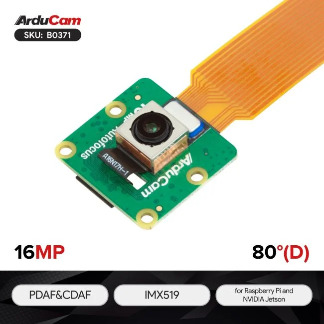
Arducam IMX519 PDAF&CDAF Autofocus Camera Module
SKU L404-033 Request quote →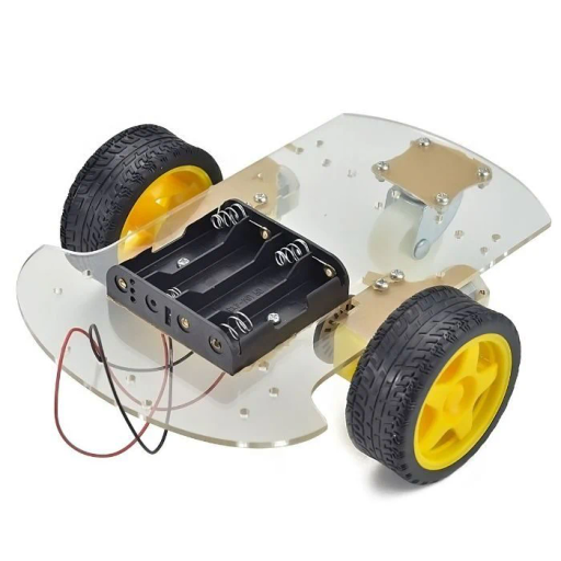
2WD Robot Car Chassis Kit
SKU L404-019 Request quote →Browse by category
Microcontrollers
10Arduino, ESP32, ESP8266 and other microcontroller boards - the brains behind embedded, IoT and robotics projects.
Explore →Sensors
29Ultrasonic, IR, temperature, humidity, motion, current, IMU and environmental sensors for prototyping, research and production.
Explore →Single-Board PC
13Raspberry Pi and other single-board computers for vision, edge AI, automation and lab workstations.
Explore →Motors
8DC, stepper and geared motors for robotics, mechatronics and automation builds.
Explore →Modules
11Communication, control and breakout modules - Bluetooth, Wi-Fi, RF, relay and more.
Explore →Power
10Batteries, power supplies, regulators, converters and protection for reliable embedded power.
Explore →LEDs & Light
13Indicator LEDs, addressable strips, matrices and displays for lighting and signaling.
Explore →Components
8Resistors, capacitors, transistors, diodes, ICs and discrete components for any bench.
Explore →Cables & Connectors
11Jumpers, headers, JST/Dupont connectors, USB, ribbon and power cables in common formats.
Explore →Prototyping
16Breadboards, jumper wires, perf boards and prototyping accessories for fast bench builds.
Explore →Servos
2Standard and continuous-rotation servo motors for precise positioning in robotics and animatronics.
Explore →Displays
1LCD, OLED, TFT and segment displays for instruments, dashboards and embedded UIs.
Explore →Kits
10Curated starter and project kits for students, teaching labs and rapid prototyping.
Explore →General
46Miscellaneous accessories, tools and frequently-stocked items for everyday lab work.
Explore →Send your parts list.
Formal quote inside 24 business hours.